Alvetex Scaffold Application Note 08
Alvetex Perfusion Plate: Dynamic Circulation and Perfusion of Culture Medium Within a Multi-welled Plate
Download this application note as a PDF (9.8 MB)
Overview
Much of our understanding of cell biology and the molecular mechanisms that control cell growth, differentiation and function in health and disease is a result of studying cells cultured on flat polystyrene substrates in flasks and dishes. However, within such environments, tissue architecture is lost, cell-cell interactions are reduced, and cells adapt abnormally to their two-dimensional (2D) surroundings by flattening and altering their gene transcription, protein translation and functional phenotype. In contrast, three-dimensional (3D) cultures more closely resemble cells in real tissues and as a consequence show significantly enhanced structure and function.
To further enhance the cell culture environment it is important to consider other factors such as the maintenance of the culture conditions over time. Tissues and organs of the body are continuously perfused by the blood circulatory and lymphatic systems, which together ensure a constant refreshment of nutrients and removal of waste products (Figure 1A). In conventional cell culture there is no equivalent arrangement, other than the frequent manual changing of the culture media. Whilst the circulatory system in real tissues is dynamic, cell culture media do not circulate or perfuse about the cells, resulting in a static model primarily reliant upon diffusion of molecules (Figure 1B). Furthermore, nutrients and waste product levels are artificially regulated as a consequence of media changing. This can result in uneven homeostasis and metabolic shock to cells exposed to changes in used and fresh culture media. Perfusion of culture media can overcome some of these issues and further augment the culture model (Figure 1C). Such dynamic flow can also be controlled to reduce unstirred layers to improve diffusion and introduce shear stresses to effect cell behaviour.

Figure 1. Schematics illustrating flow of nutrients and waste products from cells in real tissues and cell-based 3D constructs grown in vitro using Alvetex technology. A: Simplification of the capillary bed to show delivery of nutrients to cells within real tissue. The arterial system (red) brings oxygenated blood and nutrients into tissues, whilst the venous (blue) and lymphatic (not shown) systems remove waste products. B: ‘Static 3D culture’ where molecules diffuse into and out of (thin arrows) the tissue-like mass and exchange between cells and the incubating culture medium. C: ‘Dynamic 3D culture’ that also relies on diffusion but where media is continuously circulated and refreshed, disturbing un-stirred layers, and promoting greater exchange of molecules into and out of (thick arrows) the tissue-like mass.
REPROCELL specialises in the development of innovative technology to enhance the growth of mammalian cells in vitro through modification of the cell culture environment. It has developed several different products and strategies to enable scientists to construct more advanced cell-based models and assays. REPROCELL manufactures and markets Alvetex, which is a key platform technology that enables routine 3D culture. Alvetex is extremely versatile and has been employed for a broad range of applications including generation of numerous organotypic co-culture models. To further advance cell culture capability, REPROCELL has now also launched its unique Alvetex Perfusion Plate product, which provides the opportunity for dynamic media flow and perfusion across cells cultured in 2D and/or 3D. This application note provides an overview of REPROCELLʼs Alvetex Perfusion Plate and an example method for its use.
Product Description
The design of the Alvetex Perfusion Plate is based on a typical 6-well multi-welled culture plate footprint commonly used in the laboratory (Figures 2 and 3). The plate is manufactured from non-tissue culture treated polystyrene. It is supplied in a blister pack and is sterile. The plate includes a lid and Leur-lock fittings for tube attachment. As can be seen, two of the wells have been sacrificed to create space for sampling wells, the Leur-lock fittings and attachment of tubing (Figure 3B). There are four standard wells in the plate in which cell culture can be performed. Each well is linked to the next by a channel such that unidirectional flow of media can be established through the plate (Figure 4A). Well inserts can fit into the wells of the Alvetex Perfusion Plate and circulating media can support the growth of cells within them. The height of the channel entering/leaving the sampling well determines the level of the culture medium circulating within the plate. This height provides the correct level of medium for flow through the windows in the walls of the Alvetex well inserts. The channels connecting each well are angled appropriately such that media flows optimally throughout the well. Like conventional cell culture plasticware, the Alvetex Perfusion Plate is designed for use in the cell culture laboratory, within incubators, and on inverted stage microscopes. A range of laboratory pumps can be used with the plate. There are many models available and we provide an example of a peristaltic pump used in the demonstration described below.
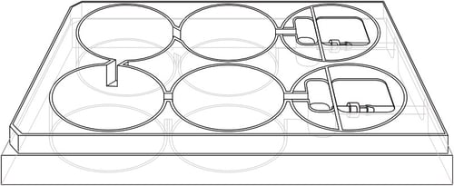
Figure 2. Design of the Alvetex Perfusion Plate. Schematic diagram showing overall plan and layout of the Perfusion Plate.
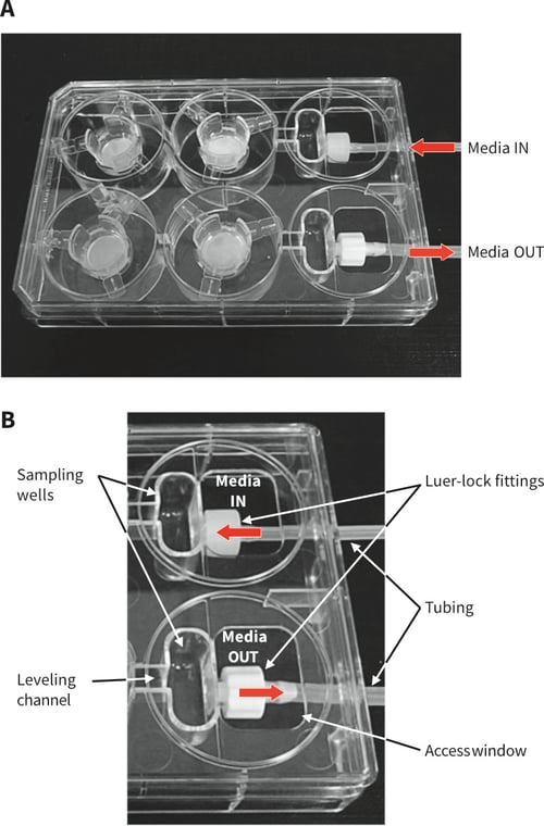
Figure 3. Design of the Alvetex Perfusion Plate. A: Photograph of Perfusion Plate with lid containing four Alvetex well inserts, Luer-lock fittings and attached tubing. B: Labelled photograph showing the sampling wells, media levelling channel, Luer-lock fittings, access window, and attached tubing. Note labelling of Media IN (1.6 mm tube) and Media OUT (2.4 mm tube), indicating unidirectional flow around the plate.
Designed With Versatility in Mind
The plate has been developed and designed such that it provides options and flexibility for the user. Here are some examples:
- The Leur-locks supplied can be inter-changed with alternative fittings. There is a range of diameters available from independent suppliers to cater for use with different sized tubing if required (see Figure 3 for Leur-lock fitment location).
- Conventional 2D culture can be performed using the Perfusion Plate (Figures 4 and 5). The plastic-ware may require coating with the appropriate cell culture reagent to promote cell adhesion (e.g. poly-D- lysine).
- For 3D culture, Alvetex well inserts can be fitted into the plate to enable 3D cell growth within a scaffold-based system (Figures 5 and 6). Alternatively, 3D culture can be achieved by other methods such as using hydrogel-based technology (e.g. Matrigel) in the
base of the well. - Tissue fragments can also be maintained and perfused with culture medium using this setup, either within a well insert or on the base of the well.
- Media flow is established through the use of an external pump (not supplied), a circuit of tubing (not supplied), and media reservoir bottle(s) (not supplied). Circulating and non-circulating setups of media flow can be established (Figure 7). Such systems can be used to condition media, or present fresh media continuously.
- The unidirectional flow between separate wells provides the opportunity to culture cells of different types and study the interaction between cell populations through the release of paracrine factors. Multiple Perfusion Plates can also be set-up in circuits of different designs connected in parallel or in series.

Figure 4. Media flow through the Perfusion Plate. A: Arrows illustrate circulation of medium around the plate through the sampling chambers and culture wells. Note that flow is unidirectional. The channels connecting each well are angled appropriately such that media flows optimally throughout the well. B: Conventional 2D culture can be performed using the Perfusion Plate as medium flow through the well. C: Well inserts of different types can be fitted into the plate, including Alvetex well inserts for 3D culture, to enable combinations of different types of culture.

Figure 5. Setting up different culture systems within the wells. A: Well inserts of different types can be fitted into the plate, including Alvetex well inserts for 3D culture. Alvetex well inserts have windows in their side wall to enable the flow of medium above and below the culture. B: 3D cultures can also be established in the base of the well and media slowly perfused above. This arrangement is compatible with both hydrogel- and scaffold-based 3D technologies. C: Conventional 2D culture in the base of the well where a monolayer of cells is established and perfused with culture medium. Note: It is also possible to place tissue fragments in a well insert or base of the well and perfuse media over them for long-term maintenance in culture.
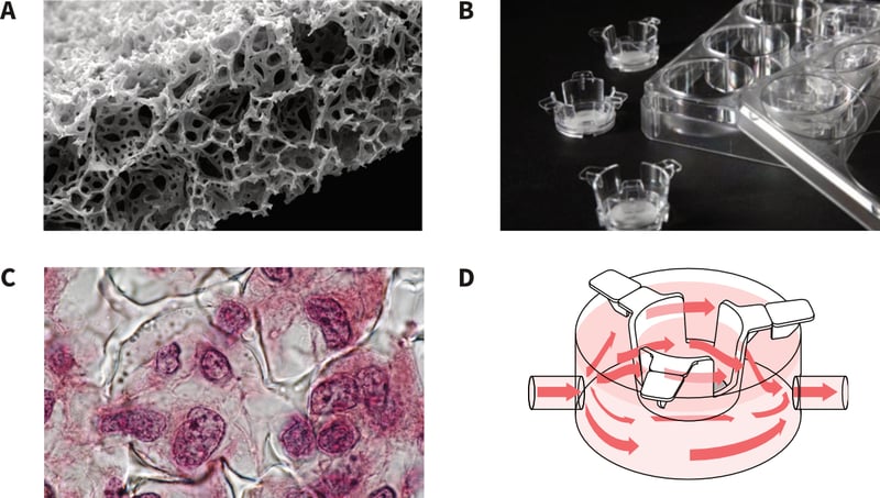
Figure 6. Use of Alvetex inserts for 3D culture and media perfusion. A: Alvetex Scaffold technology for routine 3D cell culture comes blister packed, sterile and ready for use. Alvetex comprises a highly porous polystyrene scaffold engineered into a 200 micron thick membrane. The scanning electron micrograph shows a transverse section through the membrane. B: Alvetex Scaffold is available presented within a well insert, enabling feeding of cells from above and below the membrane. 6-well and 12-well formats are available. C: Cells enter Alvetex Scaffold where they maintain their 3D structure and form interactions with adjacent cells. This results in a tissue-like structure as shown in the histology image. D: Alvetex well inserts fit inside the Perfusion Plate enabling the flow of culture medium above and below the 3D culture and free circulation through the open windows in the side wall of the insert.
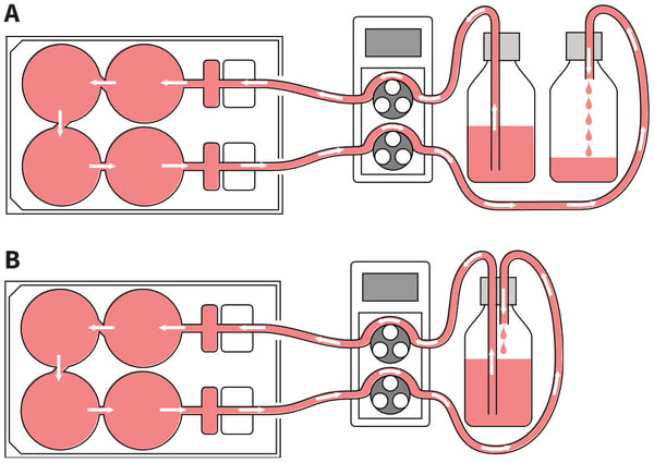
Figure 7. Setting up different circuits for medium perfusion. A: Non-circulating set-up: The Perfusion Plate can be arranged such that cells receive a continual supply of fresh culture medium. In this case the fresh medium from the reservoir is pumped around the circuit before being collected in a waste bottle. B: Circulating set-up: The same culture media pumped from the reservoir is continually circulated and returned through the plate repeatedly. This set-up is useful for generating conditioned media and concentrating factors released from the cell culture.
Materials Required
| Item | Supplier | Details/Product Code |
| Perfusion Plate | REPROCELL | AVP011-2; AVP011-10 |
| 205S/CA Multichannel Cassette Pump | Watson | 020.3704.00A |
| Silicon tubing: Media IN (1.6 mm ID) |
Sigma | T1664-25FT |
| Silicon tubing: Media OUT (2.4 mm ID) |
Sigma | T1914-25FT |
| 0.22 mm sterile filter | Millipore | SLGP033RS |
| Reservoir bottle | NUNC | Various sizes available |
| Tube connectors (1.6 mm) – optional | Value Plastics | AA-J1A 1.6 mm |
| Tube connectors (2.4 mm) – optional | Value Plastics | DD-1 2.4 mm |
| Empty 1 ml pipette tip box – optional | E.g. Starlab | – |
Example Method of Use and Setup
Here we describe a typical method of use for the Perfusion Plate. A single plate is employed in this demonstration for the re-circulating set-up. Figure 8 shows a photograph of the example method including the Perfusion Plate, pump, tubing and medium reservoir set-up on a stainless steel tray that slides into the cell culture incubator.
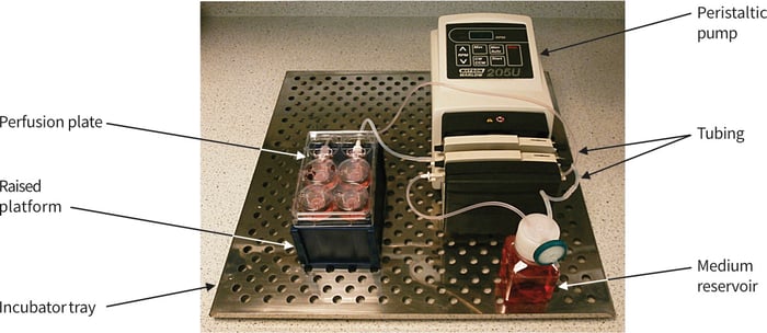
Figure 8. Photograph showing typical arrangement for the set-up of the Perfusion Plate, tubing circuit, peristaltic pump and medium reservoir. Note that the plate is raised by about 5 cm (positioned on the top of an empty pipette tip box).
Peristaltic Multichannel Cassette Pump and Tubing
The demonstration described herein is based on using a Watson Marlow peristaltic pump fitted with a multichannel cassette. It is important to note that culture medium is pumped out of the plate (Media OUT) as well as being pumped into (Media IN) the plate. The rate of medium removal from the plate needs to be same or greater than the rate of media supply to the plate. It is possible that wells will overflow should the rate of medium supply be greater than the rate of removal. In contrast, it is not possible to empty the wells. The addition of the sampling chamber and levelling channel prevents the complete removal of the medium from the culture wells and ensures that a constant level of medium is maintained. Moreover, the bore of the Leur-lock fitting and internal tubing diameter on the supply side is smaller (1.6 mm) compared to the larger diameter (2.4 mm) on the medium removal side. This further helps control that the rate of medium removal is greater than the rate of medium supply. The peristaltic pump shown in Figures 8 and 10 is a Watson-Marlow model (205S/CA) with a multichannel cassette that has 4 channels. With this pump and cassette it is possible to run two Perfusion Plates simultaneously by two separate circuits. Watson Marlow also supplies the same pump with up to 32 channels (i.e. up to ×16 Perfusion Plates; pump product code: 020.3732.00A). For the purposes of this example, two of the cassettes have been removed, leaving 2 channels for run a single plate and circuit (Figures 8-10).
Silicon tubing is connected to the Leur-lock fittings on the Perfusion plate. It is important to ensure that the 1.6 mm tubing is connected to the supply side (Media IN from the medium reservoir) and 2.4 mm tubing connected to the removal side (Media OUT return to medium reservoir or waste) (see Figures 7 and 9).
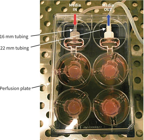
Figure 9. Photograph showing Alvetex Perfusion Plate set-up and connected to peristaltic pump. The plate has been raised by approximately 5 cm (place on an empty pipette tip box). Note the difference in the tube diameters: Media IN 1.6 mm and Media OUT 2.4 mm. The example shown includes four Alvetex well inserts within the plate with incubation medium.
For each pump channel, silicon tubing (connecting the reservoir and plate) is placed over the pump rollers (Figure 10). The pump channel cassette is used to clamp the tubing in place. The rolling action of the pump over the silicon tubing creates the desired peristaltic effect to pump the medium along the tube. It is important to note that the pump rolling action can sometimes cause the silicone tubing to be pulled in the direction the rollers are moving, creating unwanted tension and/or tubing slippage. For this particular pump we have found it important to place a tube-to-tube straight connector in the tubing (i.e. create a joint) just before the tubing enters the pump so that slippage is prevented. This straight connector acts as a barrier at the pump head cassette to prevent the tubing from moving.
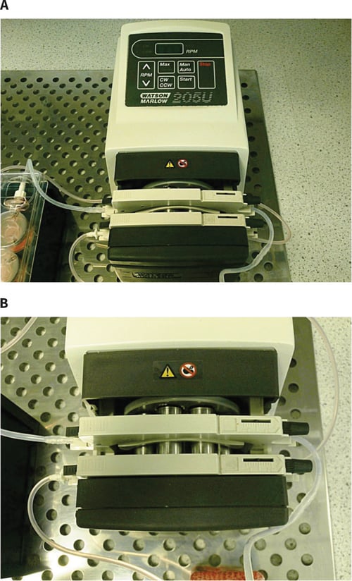
Figure 10. Photograph showing: A: Watson Marlow 205S/CA peristaltic pump with multichannel cassette; B: view of the multichannel cassette with connecting tubing and pump rollers. Note: only two of the channels are used in this particular set-up.
Media flow is altered via the pump RPM button on the keypad. The pumping direction can be altered between clockwise (CW button) and counter-clockwise (CCW). For the Watson Marlow multi-channel cassette pump (model 205S/CA) used in this example, an RPM value of 2 was selected and the direction CW. This resulted in a media flow rate of 200 mL/min. However, the flow settings should be optimised for the desired requirements of the experiment and when using different pump models.
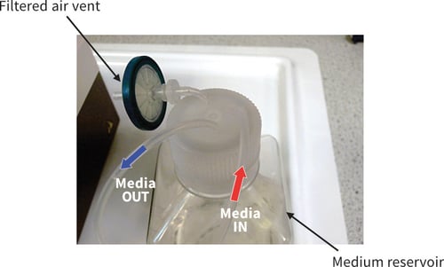
Figure 11. Photograph showing arrangement for the medium reservoir. This example was used for the recirculating set-up as illustrated in Figure 7B. The reservoir shown uses a Nunc Brand square screw top bottle. Three holes of the appropriate diameter were drilled to allow fitting of tubing: a filter is fitted to allow exchange of sterile gases; the Media IN tube, drops medium into the reservoir; the Media OUT tube draws medium from the base of the reservoir. See Figure 7 for positioning of tubing within the bottle.
Medium Reservoir
In the example shown, the media reservoir was housed in a 125 mL Nunc Brand bottle (Figure 10). Three holes of appropriate diameter were drilled into the plastic screw top cap. One hole should be used for silicon tubing transferring medium to supply the Perfusion Plate.
Another hole should be used for silicon tubing to return medium to the reservoir from the Perfusion Plate. A third hole should be used as an air vent, with tubing connected to a 0.22 μm sterile filter to prevent bottle deformation under pressure changes and allow equilibration of gases.
Note that the tubing transferring media to the plate should reach the bottom of the bottle to always ensure media is being drawn up (see Figure 6).
Additional Notes
Figure 8 shows the final perfusion set-up that should be achieved for a single circuit. All equipment should be assembled on top of an incubator shelf tray to allow easy access to and from the incubator. Plates should be placed on top of an upside-down empty pipette tip box so that tubing height remains reasonably level with the pump head cassettes. As the pump rollers are unidirectional it means that each pump head will pump medium in the same direction. In order to ensure that medium gets pumped to the plate and then back out in the other direction, some tubing needs to be looped around the pump to ensure media always travels in the right direction.
Example Protocol Using Alvetex 6-well Inserts for 3D Perfused
Cell Culture
The following protocol is an example that applies to the set-up of a re-circulating circuit using a single Perfusion Plate in conjunction with Alvetex 6-well inserts.
Seeding of cells onto Alvetex 6-well inserts
- Prepare cells and seed onto Alvetex 6-well inserts in preparation for 3D cell culture. Follow guidance as provided at protocols.
- Maintain growth of cells until ready for transfer into the Perfusion Plate.
Sterilising the Perfusion System
- The Perfusion Plate is supplied blister packed and sterile.
- Ensure tubing and reservoir bottles are sterile and ready for use in cell culture.
- If necessary, components can be rendered ʻsterileʼ by immersion in 70 % ethanol solution followed by rinsing in sterile dH2O. Autoclaving can be used if materials are compatible with this sterilisation process.
- Operate within a sterile microbiological laminar flow cabinet when constructing the circuit for perfusion and arranging the necessary components.
Perfusion set-up with Alvetex 6-well inserts
- Place 130 mL of culture media into the reservoir bottle.
- Using The Watson Marlow 205S/CA peristaltic pump, circulate the medium in the appropriate direction around the circuit (see Figures 2, 3, 6). Initially this can be done at a high flow rate to fill the system. When cells are cultured within the plate, slower flow rates are recommended (e.g. 200 μl per minute). Note flow rate settings need to be optimised in relation to pump type and model, and requirements of the experiment.
- Wait for the culture medium to fill up the system and circulate (evident by media dripping back into the media bottle). Approximately 30 ml of medium is required to fill this particular circuit and plate, leaving 100 ml in the reservoir bottle. The medium volume should remain at this level throughout the culture period. Run the perfusion system for 5 minutes and check for leaks.
- Carefully transfer the Alvetex 6-well inserts (prepared above) into the wells of the Perfusion Plate.
- Transfer the entire perfusion circuit and apparatus into the incubator, remembering to press start on the pump key-pad to initiate medium flow. Ensure that the power cable for the pump is already fed into the back of the incubator and that the incubator inlet hole (where the cable enters) is covered as much as possible with the rubber bung/ insulation. A spare power cable is recommended to allow transfer of operation between the incubator and laminar flow hood.
- Run the experiment for the desired period, changing 50 % of the media volume every 7 days.